tinysat
Once again, based on a similar project from Mohit Bhoite.
Form
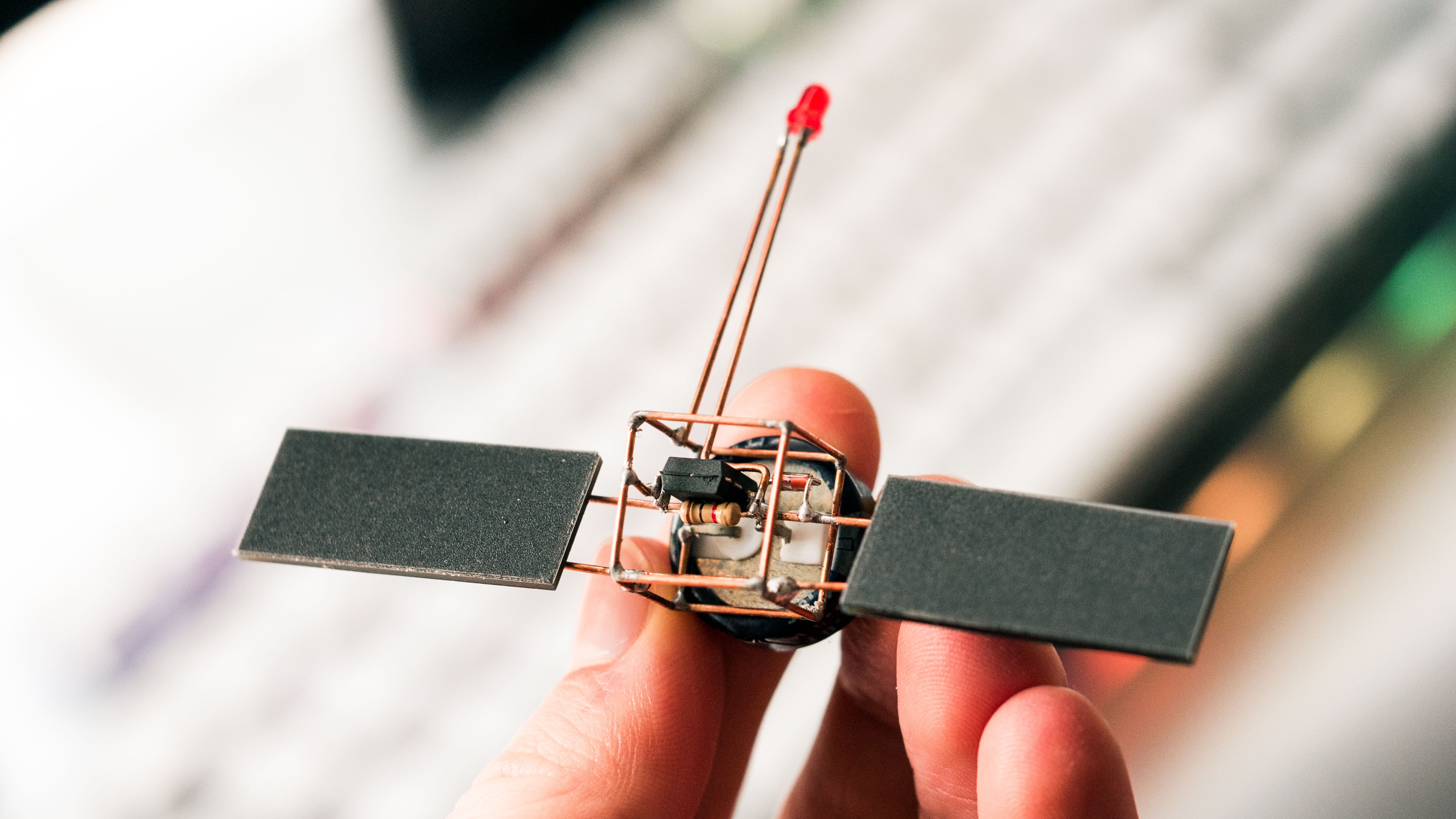
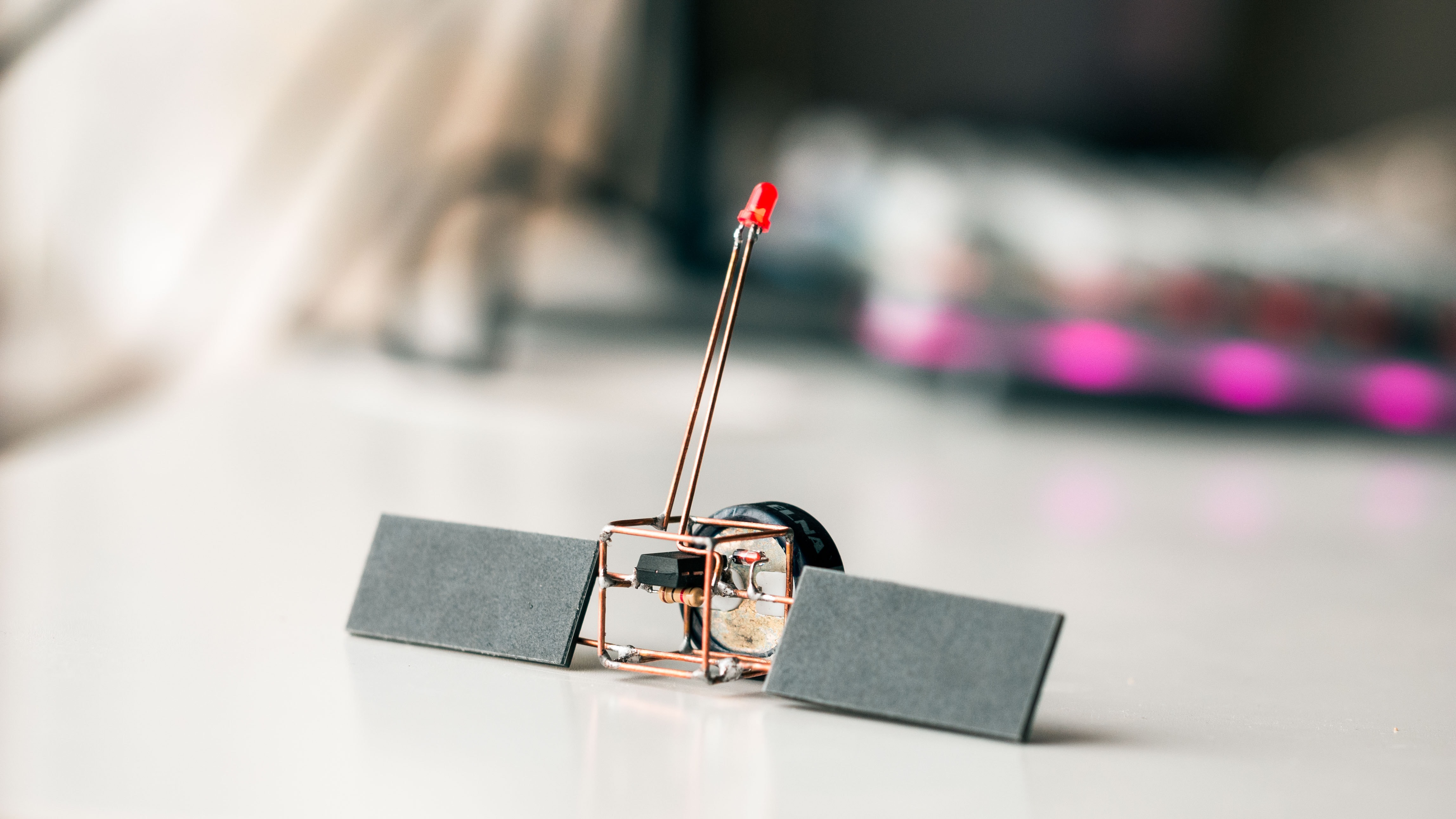
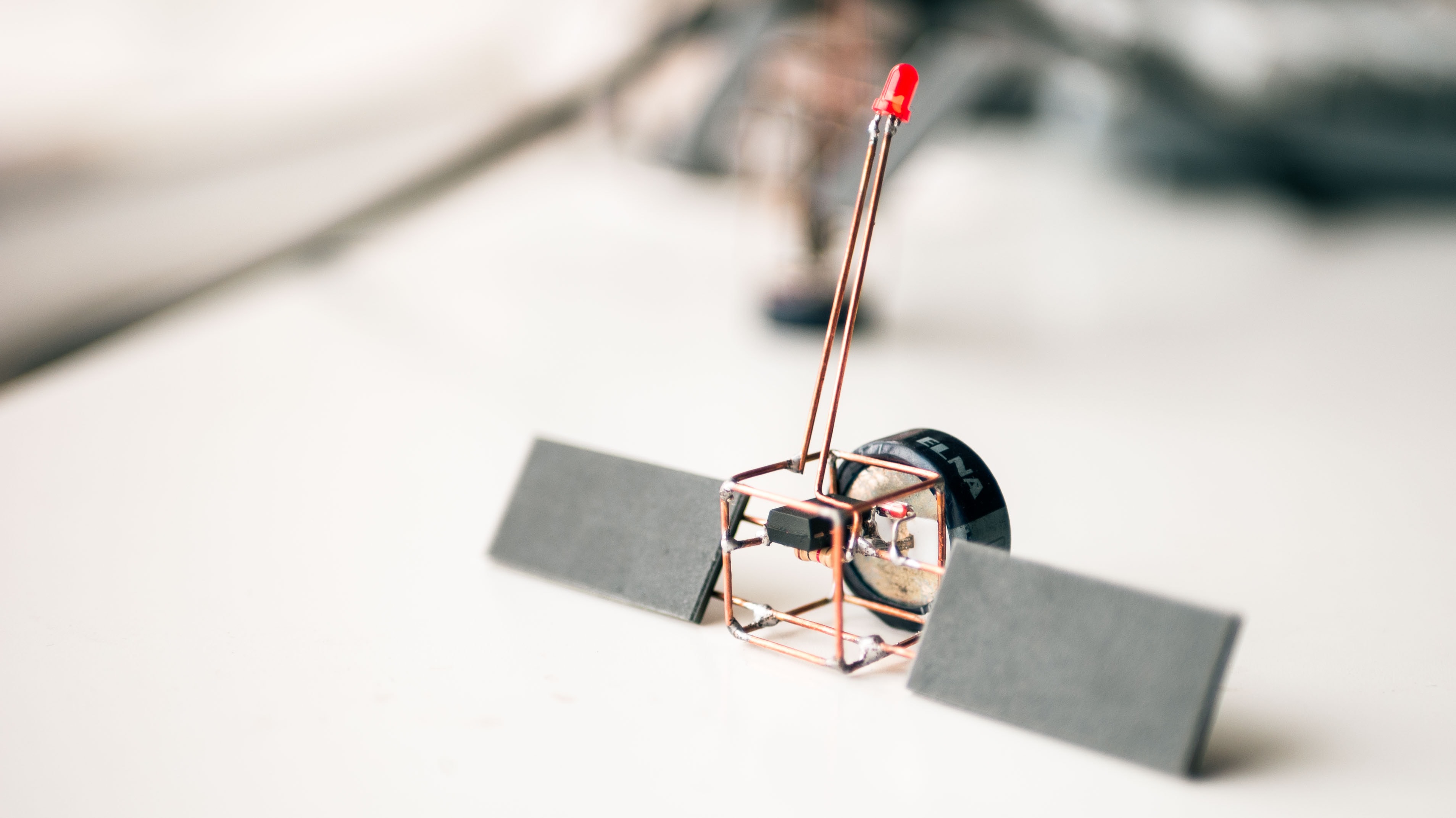
I designed this sculpture to be quite small.
The main body is a 15x15x15mm cube, containing a handful of necessary components.
tinysat is reminiscent my other sculptures, in particular 2Sat. Again, I have used 0.8mm brass wire, which by now has acquired a beautiful, oxidised-orange colour.
I intend to mount this sculpture on some sort of wooden base via a vertical brass rod, but for now, it’s free-floating. Almost like a real satellite! 🛰
Function
Rather than use discrete electronics to build this flasher, I used an ATTINY13 chip.
First, this made this project a lot simpler, as most of the functionality can be managed with software. Second, it reduced the total volume of electrical components required.
The circuit diagram for the device -
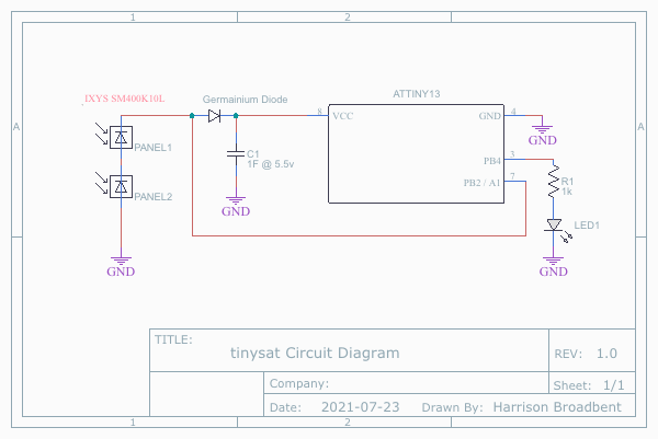
Some key points:
- A diode ensures the capacitor charge does not flow back into the panels, and powers the ATTINY only.
- In particular, I used a germanium diode instead of a silicon one. This is due to their lower forward-bias voltage (0.3V vs. 0.7V). This lets the device run for a bit longer before turning off.
- There is a feedback wire running from pin 7 of the ATTINY to the base of the diode. The solar cells have a second job as a ghetto light sensor. We read the voltage across them and use that to determine whether it is dark yet. The code below illustrates this.
The code flashed to the ATTINY13 chip -
// tinysat.ino
//

#include <avr/interrupt.h>
#include <avr/sleep.h>

/*
=====================================================
|     ATTINY13 watchdog low-power LED blinker.      |
| For use in the TinySat circuit sculpture project. |
|       ** Harrison Broadbent, July 2021 **         |
=====================================================
This program flashes an led connected to pin 3 of an ATTINY13 chip every ~10seconds.
A number of small tweaks have been added to lower the power consumption of this chip.
With a standard red 3mm led connected with a 200ohm resistor, power consumption is approx -
	off-mode: 30 μA
	on-mode : 5 mA

Code adapted from   - https://forum.arduino.cc/t/watchdog-on-attiny13-every-2-minute/570158
Project inspiration - https://www.bhoite.com/sculptures/tiny-cube-sat/

*/

int count = 0;
int darkness_threshold = 220;
int panel_voltage_reading;

// led on PB4, pin 3
// Panel voltage measure on PB2, pin 7, A1
int led_pin = 4;

// Runs every time the watchdog wakes
ISR(WDT_vect) {
	digitalWrite(led_pin, LOW);
	count++;

	// LED routine runs after an off-cycle.
	if (count > 2) {

		// only flash the LED when it's dark
		panel_voltage_reading = analogRead(A1);
		if (panel_voltage_reading < darkness_threshold) {
			digitalWrite(led_pin, HIGH);
			delay(30);
			digitalWrite(led_pin, LOW);
			delay(40);
			digitalWrite(led_pin, HIGH);
			delay(50);
			digitalWrite(led_pin, LOW);
			delay(60);
		}

		count = 0;
	}
}

void setup() {
	pinMode(A1, INPUT);
	pinMode(led_pin, OUTPUT);
	(ADCSRA &= ~(1<<ADEN)); // disable ADC; save ~320μA

	// quickly flash LED to indicate startup
	digitalWrite(led_pin, HIGH);
	delay(200);
	digitalWrite(led_pin, LOW);

	// hold LED on if it's dark
	panel_voltage_reading = analogRead(A1);
	if (panel_voltage_reading < darkness_threshold) {
		delay(500);
		digitalWrite(led_pin, HIGH);
		delay(100);
		digitalWrite(led_pin, LOW);
		delay(100);
	}

	count = 0;

	// Set countdown timer for ~8s
	WDTCR |= (1<<WDP3)|(0<<WDP2)|(0<<WDP1)|(0<<WDP0); // 8s

	// Enable watchdog & global interrupts
	WDTCR |= (1<<WDTIE);
	sei();

	// Use the power down sleep mode
	set_sleep_mode(SLEEP_MODE_PWR_DOWN);

	for (;;) {
		// sleep and wait for an interrupt
		sleep_mode();
	}
}
- We take advantage of the low-power options in this chip to reduce the idle current draw to about 30µA. This ramps up to 5mA when the LED is flashing.
- We keep the chip in low-power mode for as much time as possible. In this mode, the chip is almost completely shut down.
- The built-in watchdog timer wakes the chip every few seconds. The chip then measures the panel voltage and then flashes the LED if appropriate.
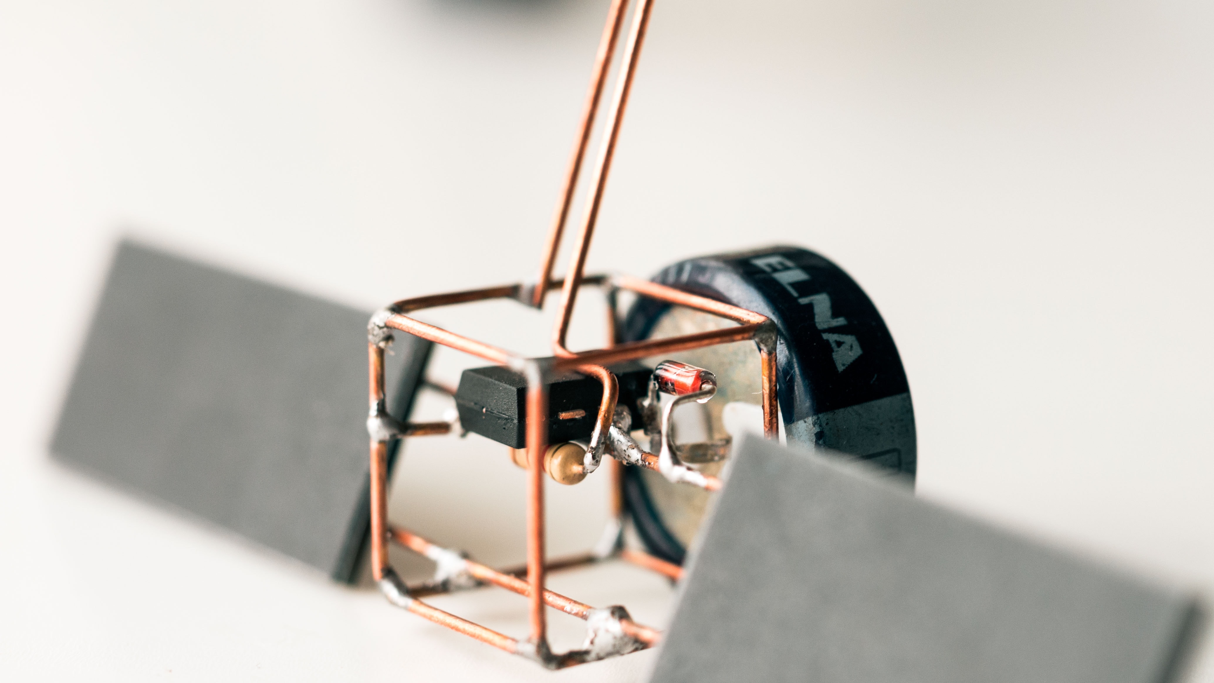
Parts
The key parts for this circuit -
- ATTINY13 microcontroller
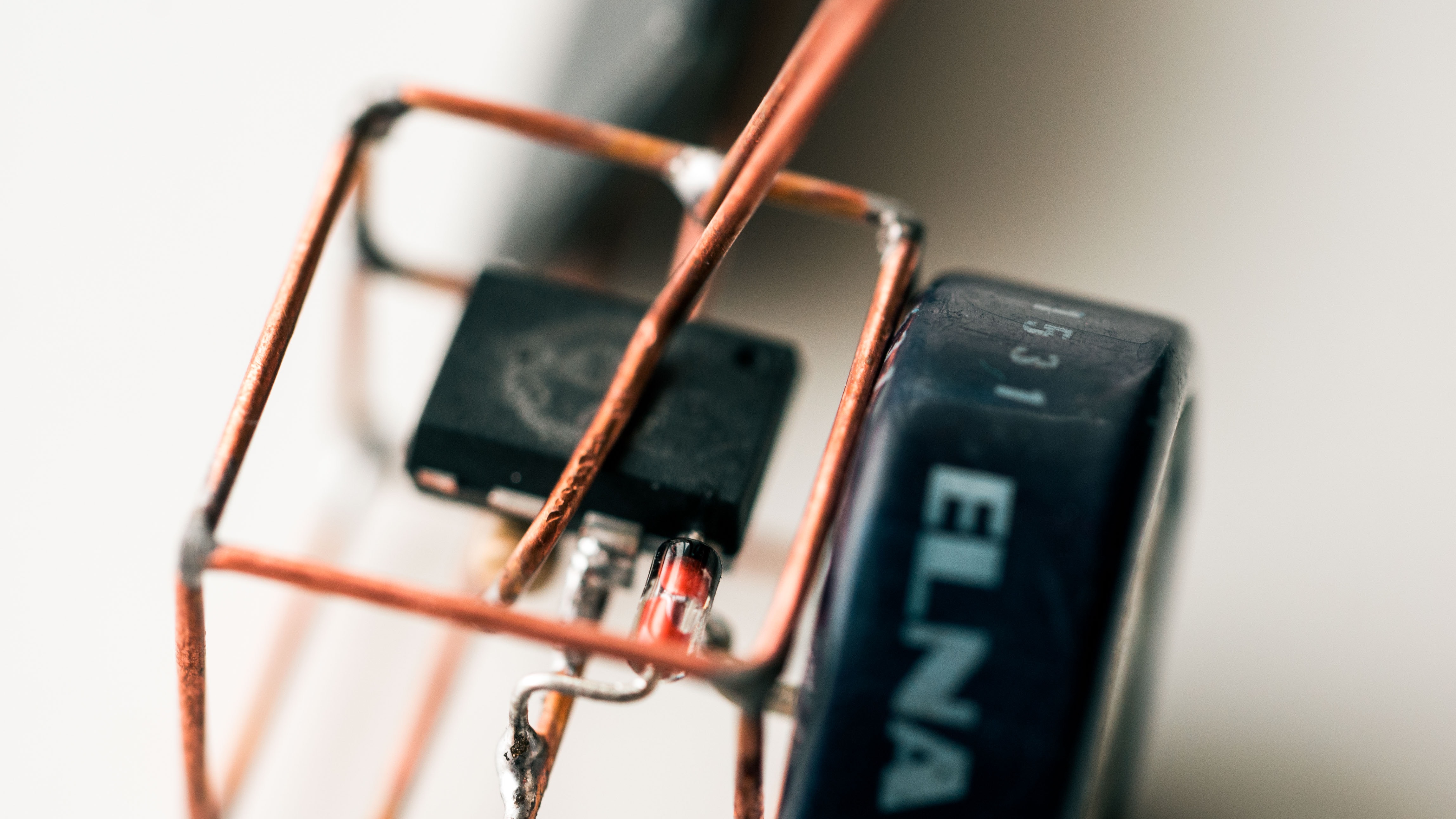
- 1F 5.5V supercapacitor
- IXYS SM400K10L monocrystalline solar cells
- Germanium diode
Gallery